- CBCT imaging is the most significant technologic advances in maxillofacial imaging since the introduction of panoramic radiograph.
- It was initially developed commercially for an angiography.
- It uses a divergent cone shaped or pyramidal shaped source of ionizing radiation and two dimensional area detector fixed on a rotating gantry, to provide multiple sequential transmission images that are integrated directly, forming volumetric information.
Princilples
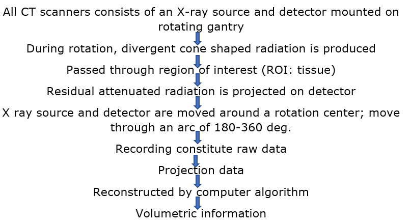

- All CT scanners consists of an x-ray source and detector mounted on a rotating gantry.
- During rotation of the gantry, the x-ray source produces radiation, while the receptor records the residual x-rays after attenuation by the patient’s tissues.
- These recordings constitute the “raw data” that is reconstructed by a computer algorithm to generate cross- sectional images.
- The basic component of the gray-scale images in the picture element(pixel) values.
- CBCT imaging is performed using a rotating platform or gantry carrying an x-ray source and detector.
- A divergent cone-shaped or pyramidal source of radiation is directed through the region of interest (ROI), the residual attenuated radiation beam is projected onto an area x-ray detector on opposite side.
- The x-ray source and detector rotate around a rotation center, fixed within the center of ROL. This rotational center becomes the center of the final acquired image volume.
- During the rotation, multiples sequential planar projection images are obtained while the x-ray source and detector move through an arc of 180 to 360 deg.
- These single projection images constitute the raw primary data and are individually referred to as basis, frame or raw images.
- There are usually several hundred two-dimensional basis images from which the image volume is calculated and constructed.
- The complete series of images is referred to as the projection data. The softwares including algorithms are applied to these projection data to generate a volumetric data set that can be used to provide primary reconstruction images in three orthogonal planes (axial, sagittal and coronal).
Indication/ application
- Implant site assessment: CBCT provides cross sectional images of the alveolar bone height, width, and angulation and accurately depicts vital structures i.e. Inferior alveolar dental nerve canal in mandibular or sinus in maxilla.
- Endodontics
- Identifications of potential accessory canals in teeth with suspected complex morphology
- Identification of root canal system anomalies and determination of root curvature
- Diagnosis of pathosis of non-endodontic origin.
- Intraoperative or post-operative assessment of endodontic treatment complications
- Diagnosis and management of dentoalveolar trauma
- Localization and differentiation of external from internal root resorption or invasive cervical resorption.
3. Orthodontic and three dimensional cephalometry
- Used in diagnosis, assessment and analysis of maxillofacial orthodontic and orthopedic anomalies
- Facilitates surgical exposure and planning of subsequent movement
- Assessment of palatal morphologic features and dimensions, tooth inclination and torque, characterization of alveolar bone for orthodontic mini-implant placement, available alveolar bone width for buccolingual movement of teeth.
4. Adequate visualization of TMJ, Pharyngeal airway space and soft tissue relationship
5. Three dimensional cephalometry include demonstrating and characterizing asymmetry and anteroposterior, vertical and transverse dentoskeletal discrepancies, incorporating soft tissue integument and potential for assessment of growth and development.
6. Mandibular 3rd molar position- relationship of inferior alveolar canal (IAC) to the roots of mandibular 3rd molar teeth, to minimize the likelihood of nerve damage.
7. Temporomandibular Joint
- Provides multiplanar and potentially three dimensional images of the condyle and surrounding structures to facilitate analysis and diagnosis of the bone morphology features and joint space and function.
- Imaging can depict the features of degenerative joint disease, developmental anomalies of the condyle, ankylosis and rheumatoid arthritis.
8. Maxillofacial pathosis
- Assessment of condition such as impacted canines, supernumerary teeth, fractured or split teeth, periapical lesions, periodontal diseases.
- Bening calcification (tonsilloliths, lymph nodes, salivary gland stones)
- Trauma
- Assessment of extent and degree of involvement of benign odontogenic and non- odontogenic condition.

Advantages
- Lower radiation dose than CT (Conventional)
- Lower time, space and cost than CT (Conventional)
- Greater hard time definition than medical CT
- Multiplanar reformation
- 3D volume rendering
- Better images with good spatial resolution
Disadvantages
- Higher radiation than 2D imaging
- Artifacts and scatters
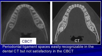
- Less soft tissue discrimination than medial CT
- Motion artifacts due to increased scan time
- Scan volume insufficiency
- Poor contrast resolution, thus soft tissue can’t be viewed
- Image noise is determental
Image artifacts
An artifact is any distortion or error in the image that is unrelated to the subject being studied.
- Inherent artifacts:
- causes- projection geometry, reduced trajectory rotational arcs, image reconstruction
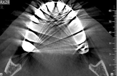
a. Scatter: Scatter results from x-ray photons that are diffracted from their original path after interactions with matter. Causes streak artifacts similar to artifacts of beam hardening.
b. Partial volume averaging: occurs when selected voxel size of the scan is larger than the size of the object being imaged.
c. Cone beam effect
- Occurs especially in the peripheral portions of the scan volume
- Because of the divergence of x-ray beam as it rotates around the patient in a horizontal plane, structures at the top or bottom of the image field are exposed only when the x-ray source is on opposite side of patient.
- Result : image distortion, streaking artifacts, greater peripheral noise
- Minimized by incorporation by manufacturers of various forms of cone beam reconstruction.
2. Procedure related artifacts
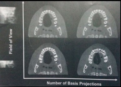
- Under sampling of object lead too noiser image
- Reduced data sample leads to misrgistration, sharp edges and noiser images.
- Scanner related artifacts appear as circular or ring streaks
- Misalignment of x-ray source to detector creates a double contour artifacts similar to that created by patient motion.
- Repeated use of CBCT equipment over time may result in slight configuration changes.
3. Introduced artifacts
a. Beam Hardening : when an X-ray beam passes through an object lower energy poton are absorbed in preference to higher energy photons.
- Cupping artifact: distortion of metallic structures as a result of differential absorption.
- Extinction or missing value artifact: Streaks and dark bands, which when present between two dense objects.
4. Patient motion artifacts
- Patient motion can cause mis-registration of data, which appears as double contours in reconstructed image.
- Problem can be minimized by restraining the head and using as short a scan time as possible.